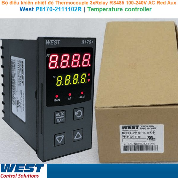
Bộ điều khiển nhiệt độ West P8170-2111102R | Temperature Controller
Specifications
| Input type |
Thermocouple |
| Option slot 1 |
Relay |
| Option slot 2 |
Relay |
| Option slot 3 |
Relay |
| Option slote A |
RS485 Communications |
| Power supply |
100-240V AC |
| Display colour |
Red upper & Lower |
| Option slot B |
Auxiliaty input (full) |
West P8170 1/8 Din Valve Motor Controller
The new Plus Series VMD Controllers have been specifically designed for open loop valve motor drive applications and feature the improved Plus Series interface and greater field flexibility.
- Jumperless Configuration
- Auto Detected Hardware
- Process & Loop Alarms
- Modbus Communications
- Auto or Manual Tuning
- Motorised Valve Control
- Valve Position Indication
- Remote/ Dual Setpoint Options
Technical Data
Features
Control Types
Full PID with Pre-tune, Self-tune and manual tuning modes.
Valve Control:
Open Loop Valve Motor Drive.
Auto/Manual:
Selectable from front panel or via digital input, with bumpless transfer.
Output Configuration Alarm 1 & 2 Types:
Up to 5 possible, two required for valve control, additional outputs for alarm, 24VDC transmitter power supply or retransmit of process value or setpoint.
Process high, process low, SP deviation, band, logical OR / AND. Also 1 loop alarm for process control security. Process alarms have adjustable hysteresis.
Human Interface
4 button operation, dual 4 digit 10mm & 8mm high LED displays, optional choice of colours (Red/Red, Red/Green, Green/Red or Green/Green), plus 5 LED indicators
PC Configuration
Off-line configuration from PC serial port to dedicated configuration socket (communications option not required). Configuration Software for Windows 98 or higher. West Part Number: PS1-CON
Input
Thermocouple
J, K, C, R, S, T, B, L, N & PtRh20%vsPtRh40%.
RTD
3 Wire PT100, 50Ω per lead maximum (balanced)
DC Linear
0 to 20mA, 4 to 20mA, 0 to 50mV, 10 to 50mV, 0 to 5V, 1 to 5V, 0 to 10V, 2 to 10V.
Scaleable -1999 to 9999, with adjustable decimal point
Impedance
>10MΩ for Thermocouple and mV ranges, 47KΩ for V ranges and 5Ω for mA ranges
Accuracy
±0.1% of input range ±1 LSD (T/C CJC better than 1°C)
Sampling
4 per second, 14 bit resolution approximately
Sensor Break
Detection <2 seconds (except zero based DC ranges), control O/P’s turn off, high alarms activate for T/C and mV ranges, low alarms activate for RTD, mA or V ranges
Outputs & Options
Control & Alarm Relays
Contacts SPDT 2 Amp resistive at 240V AC (120V AC Max for direct VMD), >500,000 operations. (1A 2xSPST 200,000 operations for Dual Relay)
Control SSR Driver Outputs
Drive capability >10V DC in 500Ω minimum
Triac Outputs
0.01 to 1 Amp AC, 20 to 280Vrms, 47 to 63Hz, 140V Max for direct VMD
DC Linear
- Outputs 0 to 20mA, 4 to 20mA into 500Ω max, 0 to 10V, 2 to 10V, 0 to 5V into 500Ω min.
- Accuracy ±0.25% at 250Ω (degrades linearly to 0.5% for increasing burden to specified limits)
- Retransmit of PV or SP Only.
Transmitter Power Supply
Output 24VDC (nominal) into 910Ω minimum to power external devices
Serial Communications
2 Wire RS485, 1200 to 19200 Baud, Modbus protocol
Digital Input
Selects between 2 setpoints or Auto/Manual control. Volt free or TTL input
Remote Setpoint / Valve
Position Auxiliary Input
- 0 to 20mA, 4 to 20mA, 0 to 100mV, 0 to 5V, 1 to 5V, 0 to 10V, 2 to 10V or ≥2KΩ Potentiometer
- Scaleable -1999 to 9999. For Valve Position Indication or Remote Setpoint Input.
- Local/Remote setpoint selected from digital input (supplied as part of Full Auxiliary) or front panel.
Operating & Environmental
Temperature & RH
0 to 55°C (-20 to 80°C storage), 20% to 95% RH non-condensing
Power Supply
100 to 240V 50/60Hz 7.5VA (optional 20 to 48V AC 7.5VA/22 to 65V DC 5 watts)
Front Panel Protection
IEC IP66 (Behind panel protection is IP20)
Standards
CE, UL & ULC recognised
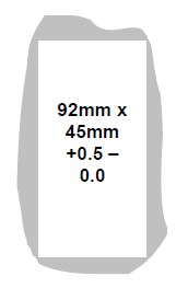
Dimensions
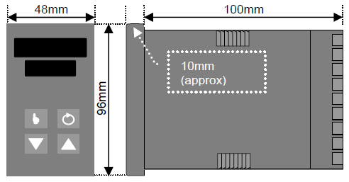 Cut out
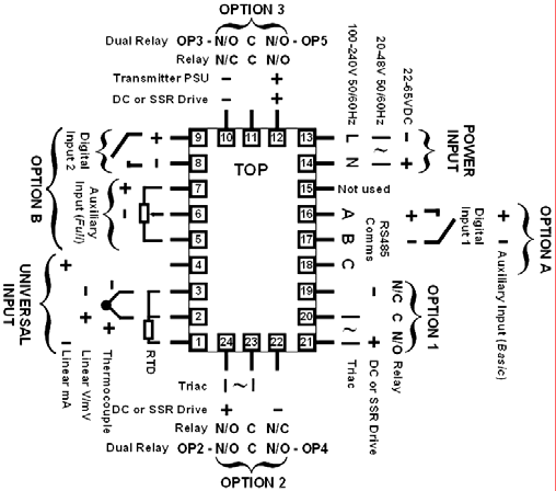
Connection Details
Field Reconfiguration
Input
Jumper-free configuration for any type
(no extra parts required)
Option Slot 1 Part Number
Relay Output ...........................PO1-C10
Linear mA/V DC Output ..........PO1-C21
SSR Driver Output ..................PO1-C50
Triac Output ............................PO1-C80
Option Slot 2 Part Number
Relay Output ...........................PO2-C10
Linear mA/V DC Output ..........PO2-C21
SSR Driver Output ..................PO2-C50
Triac Output ............................PO2-C80
Dual Relay Output……………PO2-W09
Option Slot 3 Part Number
Relay Output ...........................PO2-C10
Linear mA/V DC Output ..........PO2-C21
SSR Driver Output ..................PO2-C50
24VDC Transmitter PSU........ PO2-W08
Dual Relay Output……………PO2-W09
Option Slot A Part Number
Digital Input ............................ PA1-W03
Auxiliary Input (Basic) ............ PA1-W04
RS485 Comms....................... PA1-W06
Option Slot B Part Number
Auxiliary Input (Full) ...............PB1-W0R
Order Code
P8170 - (
A) - (
B) - (
C) - (
D) - (
E) - (
F) - (
J) - (
H)
(
A): Input Type
(Example: (A) = (1): 3 Wire RTD or DC mV)
1: 3 Wire RTD or DC mV
2: Thermocouple
3: DC mA
4: DC Voltage 4
(
B): Option Slot 1
(B= 0 or 1 or 2 or ...8)
0: Not fitted
1: Relay
2: DC for SSR
3: DC 0-10V
4: DC 0-20mA
5: DC 0-5V
6: DC 2-10V
7: DC 4-20mA
8: Triac
(
C): Option Slot 2
(C= 0 or 1 or 2 or ...9)
0: Not fitted
1: Relay
2: DC Driver for SSR
3: DC 0-10V
4: DC 0-20mA
5: DC 0-5V
6: DC 2-10V
7: DC 4-20mA
8: Triac
9: Dual Relay
(
D) Option Slot B
(D= 0 or R)
0: Not fitted
R: Auxiliary Input (Full)
(
E) Display Colour
(E= 0 or 1 or 2 or 3)
0: Red Upper & Lower
1: Green Upper & Lower
2: Red Upper, Green Lower
3: Green Upper, Red Lower
(
F) Power Supply
(F= 0 or 2)
0: 100-240V AC
2: 24-48V AC or DC
(
J) Option Slot A
(J= 0 or 1 or 2 or ...4)
0: Not fitted
1: RS485 Communications
3: Digital Input
4: Auxiliary Input (Basic)
(
H) Option Slot 3
(H= 0 or 1 or 2 or ...9)
0: Not fitted
1: Relay
2: DC Driver for SSR
3: DC 0-10V
4: DC 0-20mA
5: DC 0-5V
6: DC 2-10V
7: DC 4-20mA
8: Transmitter Power Supply
9: Dual RelayThermocouple Relay Relay Relay RS485 100-240VAC Red Aux


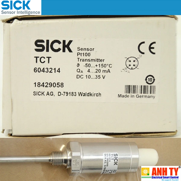 Cảm biến nhiệt độ -50...+150°C Pt100 4-20mA Sick TCT-1AAG12506MZ | 6043214Giá tốt nhất xem...0909186879 Email
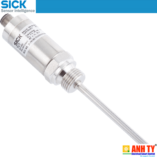 Cảm biến nhiệt độ -50...+150°C Pt100 4-20mA Sick TCT-1PAG10253MZ | 6043164Giá tốt nhất xem...0909186879 Email
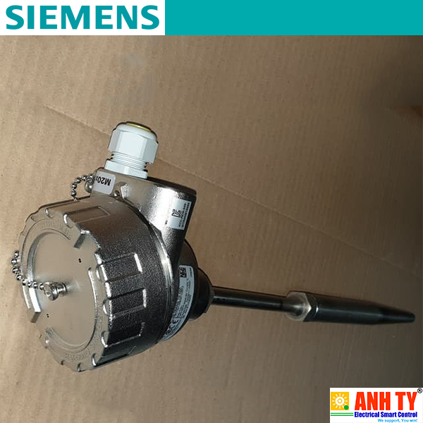 Cảm biến nhiệt độ Siemens 7MC7521-0NE00-1UB3-Z A02 C11 E00 T20 Y01Giá tốt nhất xem...0909186879 Email
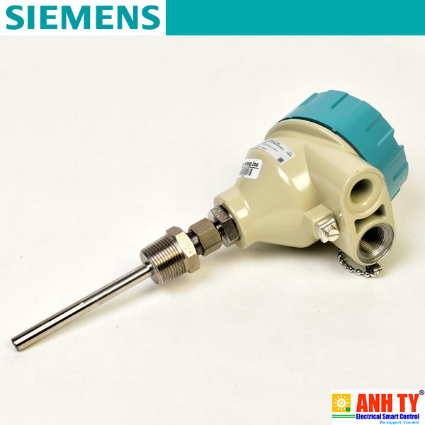 Cảm biến nhiệt độ Siemens 7MC7512-1CB25-9AK1-Z E00+N1DGiá tốt nhất xem...0909186879 Email
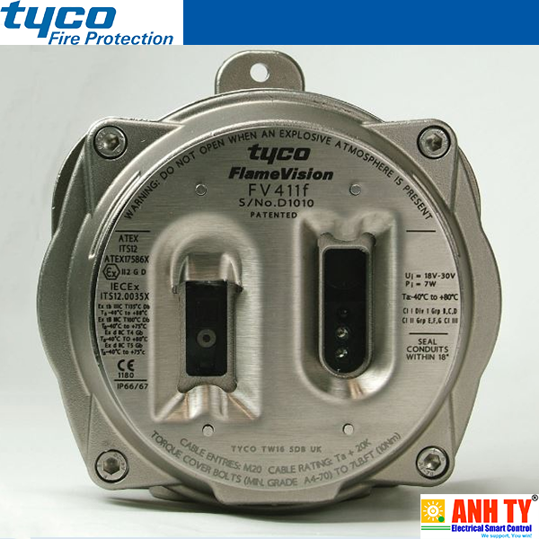 Đầu báo lửa hồng ngoại Tyco FV411f (516.300.411) | Triple IR Flame DetectorGiá tốt nhất xem...0909186879 Email
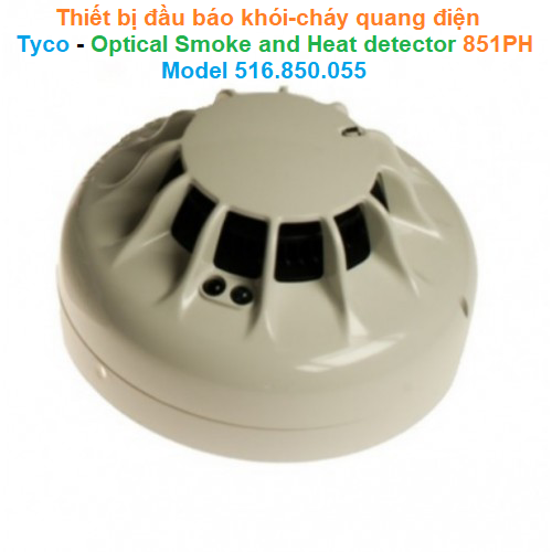 Thiết bị đầu báo khói-cháy quang điện - Tyco - Optical Smoke and Heat detector 851PH Model 516.850.055Giá tốt nhất Xem...0909186879 Email
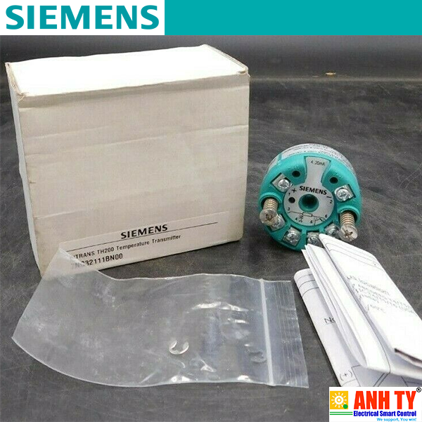 Siemens 7NG3211-1BN00 | Temperature transmitter SITRANS TH200 -Bộ chuyển phát tín hiệu nhiệt Lắp vào đầu kết nối Loại B DIN 43729 2-Wire 4-20mA Khả trình Có cách ly điện Bảo vệ nổ FM cFMUSGiá tốt nhất Xem...0909186879 Email
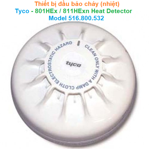 Thiết bị đầu báo cháy (nhiệt) - Tyco - 801HEx/811HExn Heat Detector Model 516.800.532Giá tốt nhất Xem...0909186879 Email
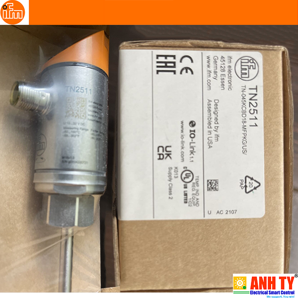 Cảm biến nhiệt độ có thông số hiển thị Temperature sensor with display - IFM - TN2511 (TN-045KCBD18-MFPKG/US/)Giá tốt nhất Xem...0909186879 Email
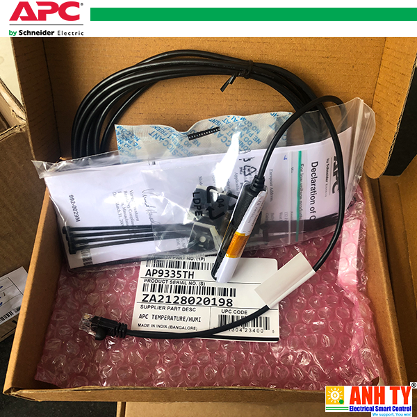 APC AP9335TH | Temperature & Humidity sensor -Cảm biến Nhiệt độ và Độ ẩm RJ45 cho Data Center or Network ClosetGiá tốt nhất Xem...0909186879 Email
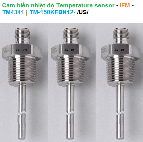 Cảm biến nhiệt độ Temperature sensor - IFM - TM4341 (TM-150KFBN12-)Giá tốt nhất Xem...0909186879 Email
 West P8170-2111102R | Temperature Controller -Bộ điều khiển nhiệt độ Giá tốt nhất Xem...0909186879 Email
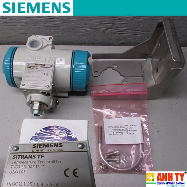 Bộ chuyển phát tín hiệu nhiệt độ Siemens 7NG3135-0AC12-ZGiá tốt nhất Xem...0909186879 Email
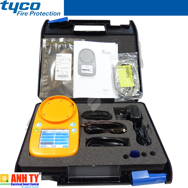 Tyco 850EMT MX Service Tool KIT -Bộ lập trình đầu báo cháy-khói cho 850 SeriesGiá tốt nhất Xem...0909186879 Email